
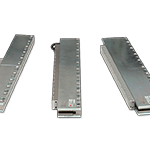
Yaskawa SGLG Linear
Kami menjual Yaskawa SGLG Linear berkualitas Original dan dijamin keasliannya. Yaskawa adalah merk dagang terkemuka yang telah dipakai hampir di semua pabrik yang ada di Indonesia. Kami siap memenuhi kebutuhan Servo & Drive Yaskawa untuk Anda dengan cepat dengan harga bersaing di seluruh Indonesia.
Precision Engineered Torque Conversion
Equip any Sigma-7 rotary servo motor with a custom-matched Yaskawa gear motor. Match the needs of a high torque, low RPM application with high-precision, low backlash inline planetary gearheads from our selection of five different gear ratios and six gearhead sizes. Each gearhead is manufactured to Yaskawa’s exacting standards and factory tested for a perfect fit.
Iron-less coil and magnet track components
Coreless GW linear servo motors are composed of moving coils and stationary magnet tracks. The moving coil has no iron content and is made of accurately resin molded motor windings. The stationary magnet track is made of two nickelized steel plates with accurately placed rare-earth magnets on each side. The steel plates are jointed at one end to form a U-channel to provide space for the moving coils.
Yaskawa SGLG Linear Features Highlights:
- Achieve smooth linear motion with an ironless design that eliminates motor cogging.
- 200 V windings
- 40 to 3000 N of peak force
- Standard and high force magnetic ways
- Zero cogging for minimal force ripple
Yaskawa SGLG Linear Models & Ratings
Standard Force Magnetic Way
| Specification | Linear Servomotor Model Number | |||||
|---|---|---|---|---|---|---|
SGLGW-30A | SGLGW-40A | |||||
050C | 080C | 140C | 253C | 365C | ||
| Rated Motor Speed (Reference Speed during Speed Control)*1 | m/s | 1.5 | 1.5 | 2.0 | 2.0 | 2.0 |
| Maximum Speed | m/s | 5.0 | 5.0 | 5.0 | 5.0 | 5.0 |
| Rated Force*1, *2 | N | 12.5 | 25 | 47 | 93 | 140 |
| Maximum Force*1 | N | 40 | 80 | 140 | 280 | 420 |
| Rated Current | ARMS | 0.51 | 0.79 | 0.80 | 1.6 | 2.4 |
| Maximum Current*1 | ARMS | 1.6 | 2.5 | 2.4 | 4.9 | 7.3 |
| Moving Coil Mass | kg | 0.10 | 0.15 | 0.34 | 0.60 | 0.87 |
| Force Constant | N/ARMS | 26.4 | 33.9 | 61.5 | 61.5 | 61.5 |
| BEMF Constant | V/(m/s) | 8.80 | 11.3 | 20.5 | 20.5 | 20.5 |
| Motor Constant | N/√W | 3.66 | 5.63 | 7.79 | 11.0 | 13.5 |
| Electrical Time Constant | ms | 0.4 | 0.4 | 0.4 | 0.5 | 0.5 |
| Mechanical Time Constant | ms | 7.5 | 4.7 | 5.6 | 5.0 | 4.8 |
| Thermal Resistance (with Heatsink) | K/W | 5.19 | 3.11 | 1.67 | 0.87 | 0.58 |
| Thermal Resistance (without Heatsink) | K/W | 8.13 | 6.32 | 3.02 | 1.80 | 1.23 |
| Magnetic Attraction Force | N | 0 | 0 | 0 | 0 | 0 |
| Combined Magnetic Way, SGLGM- | 30☐☐☐A | 40☐☐☐C☐ | ||||
| Combined Serial Converter Unit, JZDP-☐☐☐☐ | 250 | 251 | 252 | 253 | 254 | |
| Applicable SERVOPACKs | SGD7S- | R70A | R90A | R90A | 1R6A | 2R8A |
| SGD7W- | 1R6A | 1R6A | 1R6A | 1R6A | 2R8A | |
- These values are for operation in combination with a SERVOPACK when the temperatur of the armature winding is 100°C. The values for other items are at 20°C. These are typical values.
- The rated forces are the continuous allowable force values at a surrounding air temperature of 40°C with an aluminum heat sink of the dimensions given in the following table.
- Heat Sink Dimensions
- 200mm x 300mm x 12mm: SGLGW-30A050C, -30A080C, -40A140C, and -60A140C
- 300mm x 400mm x 12mm: SGLGW-40A253C and -60A253C
- 400mm x 500mm x 12mm: SGLGW-40A365C and -60A365C
- 800mm x 900mm x 12mm: SGLGW-90A200C, -90A370C, and -90A535C
- Heat Sink Dimensions
| Specification | Linear Servomotor Model Number | ||||||
|---|---|---|---|---|---|---|---|
SGLGW-60A | SGLGW-90A | ||||||
140C | 253C | 365C | 200C | 370C | 535C | ||
| Rated Motor Speed (Reference Speed during Speed Control)*1 | m/s | 2.3 | 2.3 | 2.3 | 1.8 | 1.5 | 1.5 |
| Maximum Speed | m/s | 4.8 | 4.8 | 4.8 | 4.0 | 4.0 | 4.0 |
| Rated Force*1, *2 | N | 70 | 140 | 210 | 325 | 550 | 750 |
| Maximum Force*1 | N | 220 | 440 | 660 | 1300 | 2200 | 3000 |
| Rated Current | ARMS | 1.2 | 2.2 | 3.3 | 4.4 | 7.5 | 10.2 |
| Maximum Current*1 | ARMS | 3.5 | 7.0 | 10.5 | 17.6 | 30.0 | 40.8 |
| Moving Coil Mass | kg | 0.42 | 0.76 | 1.1 | 2.2 | 3.6 | 4.9 |
| Force Constant | N/ARMS | 66.6 | 66.6 | 66.6 | 78.0 | 78.0 | 78.0 |
| BEMF Constant | V/(m/s) | 22.2 | 22.2 | 22.2 | 26.0 | 26.0 | 26.0 |
| Motor Constant | N/√W | 11.1 | 15.7 | 19.2 | 26.0 | 36.8 | 45.0 |
| Electrical Time Constant | ms | 0.45 | 0.45 | 0.45 | 1.4 | 1.4 | 1.4 |
| Mechanical Time Constant | ms | 3.4 | 3.1 | 3.0 | 3.3 | 2.7 | 2.4 |
| Thermal Resistance (with Heatsink) | K/W | 1.56 | 0.77 | 0.51 | 0.39 | 0.26 | 0.22 |
| Thermal Resistance (without Heatsink) | K/W | 2.59 | 1.48 | 1.15 | 1.09 | 0.63 | 0.47 |
| Magnetic Attraction Force | N | 0 | 0 | 0 | 0 | 0 | 0 |
| Combined Magnetic Way, SGLGM- | 60☐☐☐A | 90☐☐☐C☐ | |||||
| Combined Serial Converter Unit, JZDP-☐☐☐☐ | 258 | 259 | 260 | 264 | 265 | 266 | |
| Applicable SERVOPACKs | SGD7S- | 1R6A | 2R8A | 5R5A | 120A | 180A | 200A |
| SGD7W- | 1R6A | 2R8A | 5R5A | – | – | – | |
- These values are for operation in combination with a SERVOPACK when the temperatur of the armature winding is 100°C. The values for other items are at 20°C. These are typical values.
- The rated forces are the continuous allowable force values at a surrounding air temperature of 40°C with an aluminum heat sink of the dimensions given in the following table.
- Heat Sink Dimensions
- 200mm x 300mm x 12mm: SGLGW-30A050C, -30A080C, -40A140C, and -60A140C
- 300mm x 400mm x 12mm: SGLGW-40A253C and -60A253C
- 400mm x 500mm x 12mm: SGLGW-40A365C and -60A365C
- 800mm x 900mm x 12mm: SGLGW-90A200C, -90A370C, and -90A535C
- Heat Sink Dimensions
High Force Magnetic Way
| Specification | Linear Servomotor Model Number | ||||||
|---|---|---|---|---|---|---|---|
SGLGW-40A | SGLGW-60A | ||||||
140C | 253C | 365C | 140C | 253C | 365C | ||
| Rated Motor Speed (Reference Speed during Speed Control)*1 | m/s | 1.0 | 1.0 | 1.0 | 1.0 | 1.0 | 1.0 |
| Maximum Speed | m/s | 4.2 | 4.2 | 4.2 | 4.2 | 4.2 | 4.2 |
| Rated Force*1, *2 | N | 57 | 114 | 171 | 85 | 170 | 255 |
| Maximum Force*1 | N | 230 | 460 | 690 | 360 | 720 | 1080 |
| Rated Current | ARMS | 0.80 | 1.6 | 2.4 | 1.2 | 2.2 | 3.3 |
| Maximum Current*1 | ARMS | 3.2 | 6.5 | 9.7 | 5.0 | 10.0 | 14.9 |
| Moving Coil Mass | kg | 0.34 | 0.60 | 0.87 | 0.42 | 0.76 | 1.1 |
| Force Constant | N/ARMS | 76.0 | 76.0 | 76.0 | 77.4 | 77.4 | 77.4 |
| BEMF Constant | V/(m/s) | 25.3 | 25.3 | 25.3 | 25.8 | 25.8 | 25.8 |
| Motor Constant | N/√W | 9.62 | 13.6 | 16.7 | 12.9 | 18.2 | 22.3 |
| Electrical Time Constant | ms | 0.43 | 0.43 | 0.43 | 0.45 | 0.45 | 0.45 |
| Mechanical Time Constant | ms | 3.7 | 3.2 | 3.1 | 2.5 | 2.3 | 2.2 |
| Thermal Resistance (with Heatsink) | K/W | 1.67 | 0.87 | 0.58 | 1.56 | 0.77 | 0.51 |
| Thermal Resistance (without Heatsink) | K/W | 3.02 | 1.80 | 1.23 | 2.59 | 1.48 | 1.15 |
| Magnetic Attraction Force | N | 0 | 0 | 0 | 0 | 0 | 0 |
| Combined Magnetic Way, SGLGM- | 40☐☐☐A-M | 60☐☐☐C☐-M | |||||
| Combined Serial Converter Unit, JZDP-☐☐☐☐ | 255 | 256 | 257 | 261 | 262 | 263 | |
| Applicable SERVOPACKs | SGD7S- | 1R6A | 2R8A | 3R8A | 1R6A | 3R8A | 7R6A |
| SGD7W- | 1R6A | 2R8A | 5R5A | 1R6A | 5R5A | 7R6A | |
- These values are for operation in combination with a SERVOPACK when the temperatur of the armature winding is 100°C. The values for other items are at 20°C. These are typical values.
- The rated forces are the continuous allowable force values at a surrounding air temperature of 40°C with an aluminum heat sink of the dimensions given in the following table.
- Heat Sink Dimensions
- 200mm x 300mm x 12mm: SGLGW-40A140C and -60A140C
- 300mm x 400mm x 12mm: SGLGW-40A253C and -60A253C
- 400mm x 500mm x 12mm: SGLGW-40A365C and -60A365C
- Heat Sink Dimensions
Product Yaskawa Linear Servo Motors:
- SGLF2 Series Second generation iron-core coil and magnet track components
- SGLG Series Coreless coil and magnet track components
- SGLF Series Iron-core coil and magnet track components
- SGLT Series Balanced Iron-core coil and magnet track components
Servo & Drives Yaskawa Lainnya


